
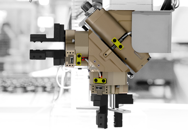
Пневмозахват может перестать уверенно удерживать деталь даже без явной поломки. Заготовка начинает проскальзывать, пальцы закрываются медленнее, положение детали повторяется хуже, а при ускорении робота или повороте узла появляется риск ее смещения.
Причина не всегда находится внутри самого захвата. На фактическое усилие и надежность удержания влияют давление воздуха у входа в устройство, качество пневмоподготовки, герметичность магистралей, геометрия рабочих пальцев, состояние поверхности детали и реальные нагрузки в цикле.
Важно различать два случая:
- снижается усилие, которое развивает захват — обычно проблема связана с давлением, утечками, загрязнением или износом;
- снижается способность удерживать деталь — причиной может быть не только сам захват, но и пальцы, масло на поверхности, увеличенный вылет, смещенный центр тяжести или ускорение робота.
1. Недостаточное давление воздуха на входе в захват
Усилие пневмозахвата зависит от давления воздуха и должно оцениваться в пределах рабочего диапазона конкретной модели. Если давление на входе ниже расчетного, кулачки развивают меньшее усилие, а при фрикционном удержании деталь может проскальзывать.
Проблема часто возникает не на регуляторе давления, а непосредственно во время цикла. На манометре перед линией может быть нормальное значение, но при одновременном срабатывании нескольких устройств давление в магистрали проседает.
На снижение давления влияют:
- недостаточная производительность пневмосети;
- неправильно подобранный регулятор;
- длинные или узкие шланги;
- ограничения в фитингах, распределителях и клапанах;
- одновременная работа нескольких потребителей;
- утечки в соединениях;
- загрязнение фильтров.
Проверять давление нужно в динамике, когда захват открывается и закрывается под рабочей нагрузкой. Сравнивать необходимо не произвольное значение в линии, а фактическое давление у входа в захват с параметрами его технической документации.
Не стоит повышать давление выше допустимого значения в паспорте модели, пытаясь компенсировать ошибку подбора. При увеличении давления возрастают нагрузки на пальцы, направляющие и корпус. По нашим рекомендациям: при давлении выше номинального длину пальцев необходимо пропорционально уменьшать.
2. Влага, масло, пыль и загрязненный сжатый воздух
Пневмозахват нельзя подключать напрямую к компрессору без подготовки воздуха. Влага, остатки масла, пыль и другие примеси попадают в пневмоканалы, воздействуют на уплотнения и подвижные элементы, ухудшают движение поршня и могут вызывать заклинивание.
Загрязненный воздух приводит к нескольким типовым проблемам:
- захват работает медленнее или неравномерно;
- пальцы не доходят до конечного положения;
- усилие открытия или закрытия становится нестабильным;
- появляются рывки при перемещении кулачков;
- ускоряется износ уплотнений и направляющих;
- засоряются мелкие отверстия и каналы;
- в холодной среде конденсат может вызвать замерзание трубопровода и ненормальную работу узла.
В нашем техническом руководстве, мы прямо указываем, что воздух после компрессора нельзя использовать без очистки фильтром: влага и пыль могут вызывать коррозию, износ, заклинивание и закупоривание малых отверстий.
Что проверить:
- установлен ли фильтр в системе подготовки воздуха;
- своевременно ли удаляется конденсат;
- не загрязнен ли фильтрующий элемент;
- соответствует ли качество воздуха условиям эксплуатации;
- нет ли масла, влаги или эмульсии в пневмолиниях;
- нужна ли для конкретной модели дополнительная продувка или пылезащитное исполнение.
3. Слишком длинные или тяжелые рабочие пальцы
Рабочие пальцы определяют, как именно захват взаимодействует с деталью. Даже правильно подобранный пневмозахват может терять эффективность, если пальцы слишком длинные, тяжелые или имеют неподходящую форму.
С увеличением вылета пальцев:
- уменьшается усилие в точке контакта с деталью;
- растет моментная нагрузка на кулачки и направляющие;
- увеличивается инерция при открытии и закрытии;
- повышается риск вибраций и перекоса;
- снижается допустимая грузоподъемность захватного узла;
- сокращается ресурс оборудования.
Пальцы должны быть максимально короткими и легкими в пределах технологической задачи. Если необходимая длина превышает допустимое расстояние захвата, рациональнее перейти на больший типоразмер или выбрать серию, рассчитанную на более высокие моментные нагрузки.
Для длинных пальцев и требовательных задач стоит рассматривать параллельные пневмозахваты VGFR с зубчатой направляющей. При выборе также необходимо учитывать допустимые моменты Mx, My, Mz и боковую нагрузку Fz, а не только усилие, указанное в таблице.
4. Утечки в пневмолинии и износ уплотнений
Утечки воздуха — одна из наиболее частых причин потери усилия и замедления цикла. Даже небольшая негерметичность на фитинге, соединении шланга или распределителе может стать критичной, если захват работает на нижней границе рабочего давления.
Проверить нужно:
- резьбовые соединения;
- фитинги и быстроразъемные соединения;
- шланги на перегибы, трещины и пережатие;
- распределительные клапаны;
- соединения на монтажных плитах;
- уплотнения поршня;
- герметичность каналов в захвате и дополнительной оснастке.
Признаки утечки не всегда очевидны. Иногда захват работает нормально без детали, но теряет скорость и удерживающую способность под нагрузкой. Другой типовой симптом — разное время открытия и закрытия или нестабильное срабатывание после нескольких циклов.
В рамках регулярного обслуживания мы рекомендуем контролировать давление воздуха, проверять состояние уплотнений и следить за чистотой направляющих.
5. Поверхность детали и неверно выбранный способ удержания
Максимальная масса детали в карточке пневмозахвата не является универсальной гарантией удержания. Она зависит от способа захвата и условий применения.
При фрикционном удержании деталь держится за счет силы трения между рабочими пальцами и поверхностью. Если поверхность покрыта маслом, СОЖ, пылью или имеет низкий коэффициент трения, фактическая удерживающая способность снижается.
Дополнительный риск создают:
- гладкая полированная поверхность;
- остатки масла и эмульсии;
- металлическая стружка в зоне контакта;
- нестабильное положение заготовки;
- большой вылет относительно точки захвата;
- смещенный центр тяжести;
- высокие ускорения робота или портала.
Для таких задач часто надежнее использовать не только фрикционное, но и геометрическое удержание: пальцы опираются на бурт, паз, выступ, отверстие или специально предусмотренный контур детали.
При подборе важно заранее определить, как именно будет удерживаться заготовка: только трением или с использованием геометрии. Этот выбор влияет на необходимый запас усилия, форму пальцев и тип захвата.
6. Неправильный размер захвата или условия работы вне допустимого диапазона
Пневмозахват должен соответствовать не только массе детали, но и реальному диапазону раскрытия, длине пальцев, моментам, частоте циклов и условиям среды.
Ошибки возникают, когда:
- модель выбрана с минимальным запасом по усилию;
- диаметр или ширина детали находятся на границе рабочего диапазона;
- пальцы выходят за допустимую длину;
- рабочая температура превышает параметры стандартного исполнения;
- захват установлен в зоне с высокой ударной нагрузкой;
- для загрязненной среды используется базовое, а не пылезащитное исполнение;
- не учитывается суммарный вес захвата, пальцев, детали и переходной плиты;
- центр тяжести сильно вынесен от кисти робота.
Для круглых деталей с торцевым захватом обычно рассматривают трехпальцевые центрирующие пневмозахваты, а для квадратных и специальных заготовок — четырехпальцевые модели. Для горизонтального перемещения круглого прутка чаще подходят двухпальцевые параллельные захваты.
Как быстро найти причину потери усилия
Проверку лучше проводить последовательно, а не заменять захват до диагностики всей системы.
- Измерьте давление у входа в захват во время цикла.
Сравните значение с рабочим диапазоном конкретной модели. - Проверьте магистрали на утечки и ограничения потока.
Осмотрите шланги, фитинги, клапаны, соединения и фильтры. - Оцените качество сжатого воздуха.
Проверьте наличие конденсата, масла, пыли и загрязнений. - Осмотрите пальцы и зону контакта с деталью.
Проверьте форму, длину, износ накладок, загрязнение и надежность крепления. - Сравните фактические условия с расчетными.
Масса детали, центр тяжести, ускорения, вылет пальцев и способ удержания должны соответствовать проектному решению. - Проверьте состояние захвата.
Оцените плавность движения кулачков, чистоту направляющих, состояние уплотнений и повторяемость конечных положений. - Проверьте датчики контроля положения.
Они помогают выявить ситуацию, когда захват не открылся или не закрылся полностью, хотя команда от системы управления уже поступила.
Как предотвратить потерю усилия пневмозахвата
Чтобы пневмозахват стабильно работал в автоматической линии, необходимы несложные доработки, а корректная инженерная база:
- выбирать модель с запасом по усилию и моментной нагрузке;
- проектировать рабочие пальцы под конкретную деталь;
- использовать фильтр и контролировать подготовку воздуха;
- регулярно проверять герметичность системы;
- не превышать допустимое давление;
- учитывать суммарную массу захватного узла и центр тяжести;
- устанавливать датчики положения для критичных операций;
- подбирать пылезащитное или термостойкое исполнение для сложных условий;
- предусматривать безопасный сценарий при падении давления.
Для задач, где остановка подачи воздуха может привести к падению детали, доступны исполнения с механической самоблокировкой. Версия NC поддерживает закрытое положение, а NO — открытое. Однако самоблокировка не отменяет необходимость проектировать общую схему безопасности роботизированной ячейки.
Когда нужна помощь инженера
Инженерный подбор необходим, если деталь тяжелая, имеет сложную геометрию, покрыта маслом, удерживается на длинных пальцах, перемещается с ускорением или должна точно устанавливаться в станок.
Для подбора отправьте чертеж или 3D-модель детали, ее массу, материал, размеры зоны захвата, положение центра тяжести, требуемое время цикла и условия эксплуатации. Специалисты KIPVALVE помогут подобрать пневмозахват, рабочие пальцы, датчики контроля положения и компоненты пневмосистемы под реальную производственную задачу.
Часто задаваемые вопросы
Можно ли увеличить усилие пневмозахвата повышением давления?
Только в пределах, указанных в технической документации конкретной модели. Давление выше допустимого может увеличить нагрузку на пальцы, направляющие и корпус, а не решить ошибку подбора.
Почему захват удерживает деталь вручную, но она выпадает при работе робота?
При движении робота появляются ускорения и инерционные нагрузки. Если центр тяжести детали вынесен, пальцы слишком длинные или поверхность скользкая, удерживающего усилия может не хватить именно в динамике.
Почему захват стал работать медленнее?
Частые причины: падение давления, загрязнение фильтра, утечки, пережатый шланг, загрязнение направляющих, износ уплотнений или ограничение потока в клапане и фитингах.
Нужны ли датчики положения для пневмозахвата?
Для критичных операций — да. Датчики позволяют контролировать, достигли ли кулачки заданного положения, и помогают системе управления остановить цикл до подачи детали в станок или оснастку.
Дата публикации: